Best practices: Assemblies

How do you create assemblies that make sense to your colleagues?
How do you keep large assemblies from becoming sluggish and unworkable?
I’ll show you how.
Just promise me you’ll pass along this knowledge to your colleagues.
In this post, you’ll find
- How to create good templates
- The first component is special
- Make quick mockups with virtual parts
- Create assembly configurations
- How to keep parts moving with limit mates
- Model assembly machining within the assembly
- How to keep large assemblies fast
- Perform regular checks
- Final words
1. How to create good templates
With templates, you make sure that all assemblies in your company or project have identical properties.
These properties included units, dimension precision, image quality and many, many more.
1a. Do this first: create a new template every year
Every time you switch to a new SOLIDWORKS version, you should create new templates.
Use the ones supplied by SOLIDWORKS, make your changes and save them for all to use.
This is official advice by SOLIDWORKS because it prevents all kinds of instabilities and strange errors caused by reused templates.
I wrote a post on how to create fresh templates from scratch here.
1b. A quick tip: Add x-, y- and z-axes to your templates
These axes are great for creating robust mates. Because these axes will always be present, these mates will rarely break.
You can also add a few custom properties to the templates.
1c. How to save an assembly template
You can create an assembly template by creating a new assembly and clicking Save As. You can now select Assembly Templates (*.ASMDOT) as the file type.
Make sure you save the file in the right directory though. SOLIDWORKS changes the directory when you switch the file type to assembly templates.
2. The first component is special
The component at the top of your assembly tree should have earned its pole position.
It should be the basis on which the entire assembly is built. It can be a model of the surroundings. Or the frame of the machine.
Remove the fixed property (right-click > Float) immediately after inserting the component, don’t be lazy.
After that, make sure it is properly mated in place. That means using an origin coincident mate or creating three coincident mates on the assembly planes.
3. Make quick mockups with virtual parts
Virtual parts are not actual files, because they are saved internally in the assembly file.
You can use them to quickly model concepts, they behave mostly like normal parts. That means you can add configurations, mates and colors to them.
Just make sure you save the virtual parts as real files somewhere along the road in your design process. Virtual parts increase the size of the assembly and you can easily lose changes. Also, PDM doesn’t notice virtual parts.
If you want to know more, check out our article on virtual parts.
4. Create assembly configurations
If you ever created parts or assemblies that were nearly identical, you now that configurations can a blessing.
Configurations allow you to vary:
- The suppression state of:
- Parts
- Subassemblies
- Mates
- Mate dimensions
- Part/assembly configurations
- Materials
- Display states
The list is not exhaustive, but these are the properties that I vary most often. You can find a basic video tutorial on configurations here.
5. How to keep parts moving with limit mates
I want my 3D models to be a proper representation of the real world.
So if a part should move in real life, it should move in the assembly.
You can do this by adding a Limit Distance or Limit Angle mates. You can find these mates in the Advanced tab of the mates window.
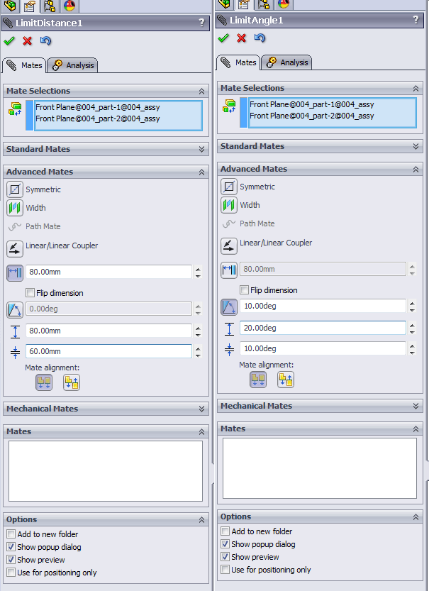
Limit Distance and Limit Angle mates will allow and limit component movements
When you insert an assembly with moving parts into a higher assembly, part movements are disabled by default.
If you want to allow those movements in the top assembly as well, you have to edit the properties by right-clicking the subassembly in the tree and opening the properties window.
You can now set the assembly to from “Rigid” to “Flexible” and voila.
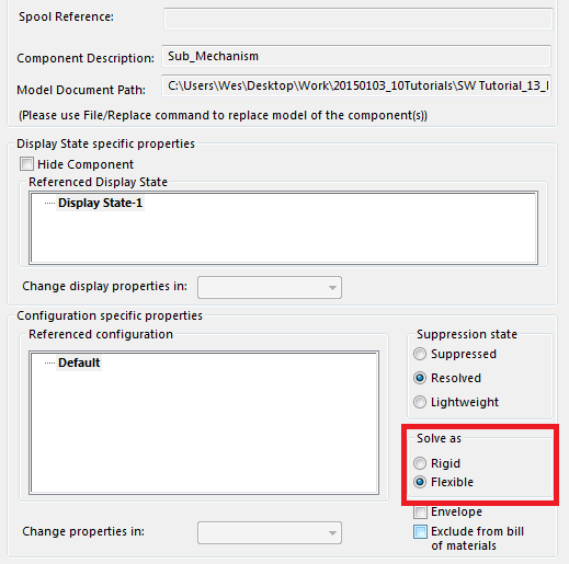
Enabling movement in subassemblies
You can find a more in-depth tutorial on rigid/flexible assemblies at 3DEngr.com. We found the image above there as well.
Just remember that flexible assemblies are bad for performance. Advanced mates are also approximately 10 times slower than standard mates.
6. Model assembly machining within the assembly
When you weld or bolt together parts, then machine them afterward, you should model the machined features in the assembly as well.
You shouldn’t extrude holes in parts and then hide them using configurations, you will only create confusion and you will increase the chance on errors in manufactured parts.
The assembly tab in the Command manager holds all kinds of ways to shoot holes in your assembly.
Notice there are no extrusion features present, you can only remove material.
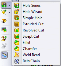
Assembly machining
Ditch the Toolbox, once and for all
Start using the fastener library that actually follows the standards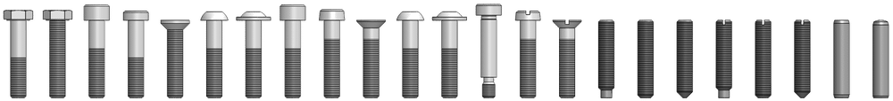
- No more mate errors
- Made for speed
- No license fees
7. How to keep large assemblies fast
It always helps to have a blazing fast PC with the latest Intel i9 septacore processor.
But if you want to keep the assembly snappy regardless of hardware requirements, here are some pointers:
- Only make subassemblies flexible when needed
- Limit the number of mates by creating subassemblies when possible.
- The feature tree shows the order in which features are created. Mates are calculated before assembly holes and patterns. So if you mate a part to a patterned part, all calculations have to start over. Every rebuild will take twice as long.
- Minimize the available degrees of freedom, so properly mate all parts
- Minimize dependencies and relations between parts and assemblies
- Minimize the number of configurations, because configs will increase the file size
- Avoid assemblies with both massive and tiny parts, because the smallest part determines the triangle size for your graphics card.
- Use Large Assembly Mode when you are dealing with massive assemblies
- Create lightweight assembly configurations with suppressed fasteners and internal components
- Use SolidWorks SpeedPak to simplify parts of your models
- Avoid virtual parts in the later stages of the design process
You can find more tips on working with large assemblies in these blog posts by SolidSmack, Javelin Technologies and Engineers rule.
How to improve assembly performance
We now offer Performance Sessions, where we’ll spend two hours going through your assembly via TeamViewer. Our goal is to improve the assembly speed and to teach you how you can prevent slowdowns.
8. Perform regular checks
The past work week was rather awful for me because I found a bunch of reasons why a design was not going to hold up in real life.
We basically had to start over, just as we were finishing the design.
That is why I really urge you to do continuous checks on your assemblies. Those checks can take place in the following forms:
- Rotate, rotate, rotate. Go get a 3D mouse at 3dconnexion.com and you’ll be able to spot issues much sooner because you will be inspecting the assembly every day from every angle.
- Make cross-sections regularly so you can spot overlaps
- Use the Assembly Visualization feature so you can spot missing materials and masses. Check out this video tutorial by CADD Edge.
- Use the Interference detection mode to check for interferences and overlaps. Video tutorial by Fisher / Unitech
- Use the Hole Alignment tool to check if holes in different parts line up. Video tutorial by CADD Edge
9. Final words
There you have it, the basics of proper assembly design.
All in all, there are five major tips:
- Create good templates
- Use configurations
- Mimic the behavior of the real thing
- Know how to prevent performance degradation
- Check for improvements every single day
I have distilled my knowledge down to a thousand words (2020 update: now 1200 words, yay). Obviously there are more great tips, so please let me know via email if I missed something.